
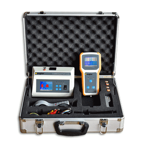
Description
- Safe to use
Grould faut locator to quickly pinpoint the fault without injecting signal to DC system. No interruption to DC system itself during signal fault location with its built-in model for current and voltage limitation. - High reliable designing
It adopts main system of 16-bit micro-processor. Hardware designing strictly follows EMC standard to ensure reliability of itself and its tested systems. - Precise measurement
It adopts high accurate current clamp for signal tracing and precise ADC for voltage sampling. This ensures the accurate measurement of voltage and resistance. - User-friendly interface
It has LCD display with vivid information indicating grounding status, waveform, insulation leveling, insulation resistance, leakage current, and direction of ground fault and so on. This user-friendly interface makes it easy and effective to use in the field. - Intelligent measurement function
- Signal analyzer can automatically identify system voltage leveling.
- When insulation resistance has any change, signal analyzer could quickly indicate the change.
- Distance will not affect the ground fault detection once the signal analyzer and detector are synchronized.
- During ground fault location, current clamp could either clamp on single cable or multiple cables for faster and more effective signal tracing.
- Signal detector will indicate the direction of ground fault on screen once it detects any insulation problem.
- Signal detector and analyzer have wireless communication. Complete measurement could handle different types of insulation problem in DC system.
- Measures voltage between DC system and ground ranging from 0 to 300V.
- Measures grounding resistance up to 999KΩ for both busbars and each branch circuit
- It detects and measures AC voltage which interrupts in DC system. Detection range is from 0 to 288V.
- Fast signal positioning for the point with ground fault in branch circuit.
- It performs the function as accurate current meter with resolution up to 0.01mA.
- It could quickly pinpoint the ground fault without injecting signal to DC system.
- Arrow indication effectively helps users trace the signal and pinpoint the ground fault.
- Display of insulation levelling after signal detection on each tested circuit branch.
- Waveform display for tested circuit, indicating insulation status and current changes in tested circuit, it help users fast and effectively locate the point with grounding fault.
Operation environment
- Temperature: -30℃~+50℃
- Humility: ≤95%
Wireless communication
- Signal power: ≤ 10dbm
- Signal frequency: 433Mhz
- Sensitivity: -106dBm
- For DC system of 48V, 110V, 220V or customized voltage level.
- Voltage range of system to ground: 0-300V
- Measurement of DC voltage to ground: 0-300V
- Measurement of AC voltage to ground: 0-300V
- AC interruption warning: ≥5V
- Voltage resolution: 0.1V
- Measurement range of system to ground: 0-999.9KΩ
- Grounding resistance resolution: 0.1KΩ
- Display: LCD
- Current detection signal: 0-2mA adjustable
- Voltage detection signal: 0-50V adjustable
- Signal frequency: 0.16Hz and optionally no-signal mode
- Anti-interference from DC distributed capacitance: 1000uF
- Power supply: powered by tested circuit
- Weight and dimension: 0.503kg, 200*117*55mm
- Insulation resistance (in signal mode)
- In 220V system: 0 -600KΩ
- In 110V system: 0 -300KΩ
- In 48V system: 0 -60KΩ
- Resistance resolution: 0.1KΩ
- Insulation resistance (in no-signal mode)
In 220V system: 0 -50KΩ
In 110V system: 0 -25KΩ
In 48V system: 0 -10KΩ
Resistance resolution: 0.1KΩ
- Waveform display time: 12 seconds
- Current measurement range: ±100mA
- Current resolution: 0.01mA
- Display: LCD
- Direction indication: forward or reverse direction indicating in arrow
- Anti-interference from DC distributed capacitance: 1000uF
- Distance from analyzer during signal tracing: no limitation
- Clamp jaw size: Ф30mm
- Power supply: 5V by 4 pieces of AA standard battery
- Weight and dimension: 0.332kg, 200*100*33mm
Q: What may happen if I don’t trace the signal fault in DC system?
A: Multiple grounds can occur on the dc system at the same time. This situation becomes critical when the combined ground resistance becomes so low that high-voltage circuit breaker control schemes are unable to open or close breakers when required or dc system circuit breakers and or fuses open due to over current resulting in de-energization of vital operating equipment.
There are some other bad consequences due to ground fault. Please click HERE for more consequences and solutions.
Q: What are the causes of DC ground fault?
A: Some common sources of low resistances to ground include:
- Moisture in conduit
- Junction boxes or switch/sensor terminations
- Wire splices soaking in water
- Degraded cable or wire insulation caused by aging
- Environmental conditions
- Wild habitat and constant abrasion from vibration
- Sharp objects piercing cable and wire insulation
- Wires that have pulled out of their terminations and touch ground or water
- Failed capacitors or semiconductor surge suppressors.
Q: What are the principles of tracing the signal fault?
A: There are 3 methods for signal tracing in circuit which is with earth fault:
1). Traditional Method: Sectionalization
Traditional ways of fault location in DC system involves sectionalization or interruption of DC branches to isolate the ground fault.
2). Current Injection
This method will inject a low-frequency AC signal and use this AC signal to locate the ground fault in the DC system.
3). Use Measurement Bridge
For online fault location, ground fault locator adopts the measurement bridge (switchable resistor) inside the signal analyzer to analyze voltage, current and grounding resistance. Then it uses signal detector to pinpoint the fault.
Q: What are the advantages of using switchable bridge (resistor) measurement?
A: It does not need injection of current signal to tested system and thus no relay tripping. It is more effective for fault location and safe to the tested circuits.
Q: How do you bypass the interference during live (online) signal tracing?
A: There is always interference caused by distributed capacitance in live (online) measurement. To bypass this interference and trace the fault faster, in firmware we use very low measurement frequency; in hardware, we use high sensitive current sensor for signal tracing.
Q: How do you avoid relay tripping during signal tracing?
A: We are using very low measurement current (lower than 5mA). This will not cause relay tripping in live signal tracing.
Customers also viewed:
Advanced model for quick detection
Quick test of battery internal resistance
With real time monitor during discharge